Fourier gratings
Developments - Workgroup for SubMillimeter and Terahertz Receivers
Introduction
Owing to their high diffraction efficiency, phase gratings are widely used in optics to shape and split monochromatic beams. With the advent of multibeam heterodyne receivers in submillimeter astronomy, they have also become popular in this part of the spectrum for local-oscillator beam multiplexing. Splitting the beam from one oscillator into a given number of equal beams by use of a phase grating is a very elegant way to distribute the local-oscillator power efficiently to an array of mixers.
Stepped grating Structures
- Standard in common optics ==> easy to develope.
- Also used in heterodyne array receivers (CHAMP of the MPIfR).
- Good, but not optimum performance
- As reflection grating (they perform better than transmission gratings) no 2-dimensional beam patterns possible, because the 2-D structures are very difficult to manufacture.
These grating structures have been the starting point in our development of a new type of grating for the use as LO-multiplexer.
Theory of Fourier gratings (FG)
A phase grating has a transmission function like
using the phase modulation at the position (x,y). The structure of a one dimensional symmetric Fourier grating is given by a finite Fourier series expansion :
where the unit cell extends from -Delta x/2 to +Delta x/2. The transmission function is accordingly written as
The diffraction pattern of the general Fourier grating is given by the Fourier transform of t(x). This results in a multiple convolution of the diffraction fields of the individual Fourier components:
where Jq(a) denotes the Bessel-function of the first kind of order q. Although this is a simple equation we can not analytically calculate the coefficients an. We thus developed a numerical optimization method to calculate them. A direct numerical FFT is usually faster than evaluating T(k), and is therefore used in our calculation process.
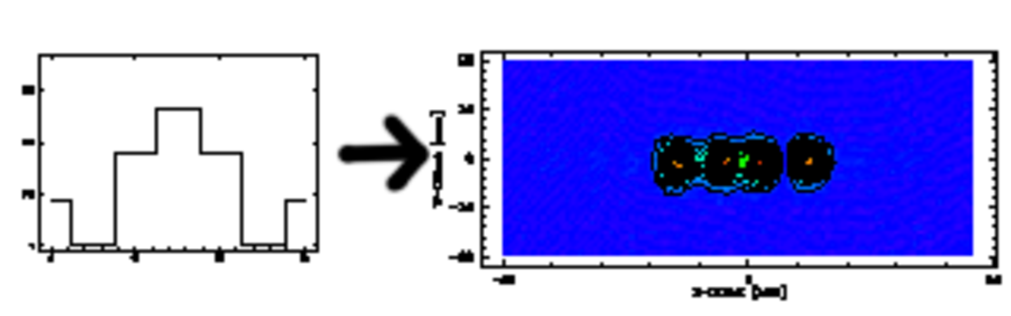
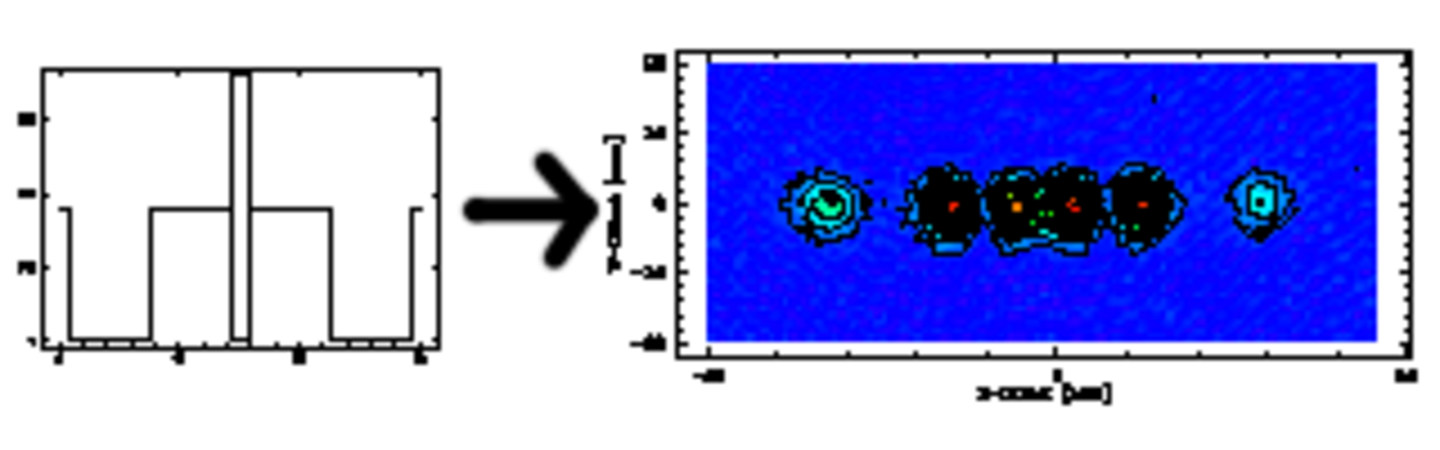
Fig. 2: Structures of 13 coefficients Fourier gratings producing 2, 5 and 8 beams (from left to right). The theoretical efficiencies are 81%, 92% and 96%.
A comparison of the intensity distribution in the diffraction pattern using a standard Dammann grating (from left to right in Fig. 3), a multilevel grating, a 13 coefficient Fourier grating and and the optimum Fourier grating (right hand panel) shows the increase of the efficiency by using our type of grating.
The efficiency of Fourier gratings producing a given number of equal beams (Fig. 4). The dotted line marks the maximum efficiency achievable with N=5 Fourier coefficients, the solid line gives the efficiency for N-->infinity.
Number of Fourier coefficients is calculated from the tradeoff between:
- minimum radius of curvature of the structure (limiting the size of the endmill)
- efficiency of the grating (grows with the number of coefficients)
==> results in approximatly 13 Fourier coefficients (Fig. 5).
Bandwidth of the gratings
Detuning the frequency results either in position errors of the beams and in a power inbalance between them. Our SIS-system can tolerate a frequency shift of approximatley +-5%. For higher bandwidth we have to exchange the grating. Because the reference planes are machined together with the grating structure, exchanging the gratings is simple and reproduceble.
1-dimensional Fourier gratings
For the calculation of one-dimensional structures we use the following 2-step method:
- Random search of a good set of coefficients an (e.g. 4 N sets for N Fourier-components). The calculated diffraction patterns of these parameter sets are evaluated by comparing the RMS deviation from the desired pattern.
- Linear optimization of the best (e.g. 20) parameter sets to get the best possible grating structure for N Fourier-components.
The grating structures can be superimposed in different orthogonal directions to get a 2-dimensional beampattern. Of course, this method only produces rectangular arrengements.
2-dimensional Fourier gratings
Calculation of two-dimensional structures:
Because of the higher number of coefficients N2 a random search is inefficient. We thus established the following method:
- Modeling the grating as a beam combiner by summing up the fields of the desired diffraction orders as plane waves on the grating plane produces a grating with varying amplitude and phase. Minimizing the amplitude variation by optimizing the phases of the incident waves and taking only the phase-variation gives a good first guess for the optimization process.
- Optimization of the best (e.g. 10) grating structures to get the optimum grating structure.
To show the power of the design process, we calculated some letters as Fourier gratings using also 13 coefficients per lateral dimension. Fig. 8 shows the unit cells of the letters (top row) and their calculated diffraction pattern. These grating structures would be very hard to manufacture as stepped gratings, but easily as Fourier gratings.
Collimating Fourier gratings (CFG)
Using planar gratings, the LO source had to be reimaged to form a plane wave at the location of the grating. The new collimating Fourier grating is matched to the wave front curvature of the divergent beam and does not require an additional collimating element. Because of the smooth grating structure it is possible to produce the collimating Fourier gratings on a commercial numerically controlled milling machine.
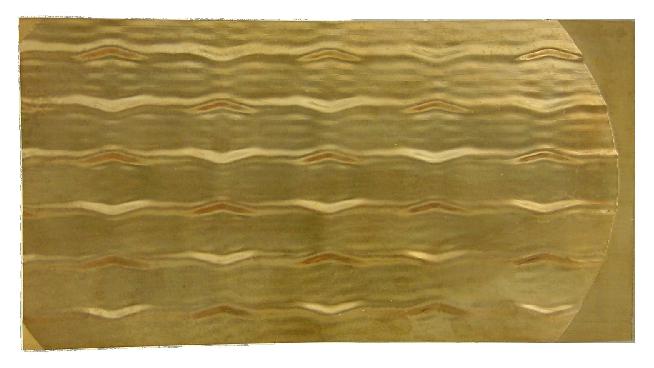
The collimating Fourier gratings can as well be manufactured easily on our in house CNC milling machine. Fig. 11 shows a photograph of the grating for the Desert-Star project. The 4 corners are manufactured as referenc planes for easy repositioning of the grating.