LINC - The Camera System
The Large Binocular Telescope (LBT) basically holds two identical primary mirrors of 8.4 meters diameter each (see the description of the telescope for details and images), which share a common mount at a linear separation of 14.4 meters (centre to centre). Using adaptive secondary mirrors and suitable wave front sensors both optical paths will be operated at the diffraction limit. The point spread function (PSF) at the individual focal planes of the respective primary mirrors therefore resembles a rotationally symmetric Airy function and the angular resolution of the two separate single dish telescopes will be about 37 milliarcseconds at the infrared J-band (lambda = 1.25 µm).
Nevertheless, this angular resolution can be increased significantly, if the correlated wavefronts of the two primary mirrors are brought to optical interference in a common focal plane. Because of the interferometric extension of the optical baseline in only one linear dimension (along the connection line of the two primary mirrors), the resulting intensity profile of an artificial point source at the interferometric focus is not any more rotationally symmetric, but is the combination of the Airy function of the single dish telescopes overlaid by the characteristic interference fringes of a dual beam interferometer. The result of a numerical simulation of the expected interferometric point spread funtion of LINC is shown in Fig. 1.

Figure 1: Numerical simulation of the expected interferometric point spread function of LINC. This image has been generated using ZEMAX® with input parameters assuming a LBT like optical assembly and a focal ratio of f/60. The circular structure (the three largest intensity peaks form an inner circular disk, which is surrounded by several small maxima arranged in an outer ring) corresponds to the Airy distribution of a single telescope aperture of 8.4 meters diameter. The overlaid parallel grating like structure (e.g. which separates the central Airy maximum into three individual peaks) corresponds to the interference fringes of a dual-beam interferometer with a baseline of 14.4 meters. In this picture the interferometric baseline is oriented along the horizontal axis of the graph.
Perpendicular to the connection line of the two main mirrors (vertical axis in Fig. 1) the angular resolution is unchanged at 37 milliarcseconds (J-band), what corresponds to the Airy distribution of a single telescope aperture of 8.4 meters. Nevertheless, in the direction parallel to the baseline (horizontal axis in Fig. 1) the angular resolution is defined by the overlaid interference fringes and improved to 9 milliarcseconds (J-band). Furthermore the orientation of the interferometric baseline (and so the axis with improved angular resolution) is not fixed in the reference frame of the observed sky but follows the daily rotation of the earth. Tracking a given astronomical source the interference pattern of LINC rotates by 180 degrees within 12 hours. Using suitable numerical algorithms and the data of several exposures, which have been taken at different times of the night, it is therefore possible to calculate a reconstructed image, which shows the improved interferometric angular resolution in both axis (and all directions in between).
Due to the fact that the two 8.4 meters primary mirrors of the LBT share a common mount their spatial separation is comparatively small at 14.4 meters. For LINC this results in an unprecedented and unique combination of high angular resolution (9 milliarcseconds at 1.25 µm), wide field of view (15 to 120 arcseconds depending on the used detector array and the performance of the complex adaptive optics system) and large collection area (120 m²).
Astronomical camera systems at other interferometric telescopes (e.g. VLTI, Keck I & II) may achieve better angular resolutions, but in general are limited to very small field of view of less than one arcsecond. The unique imaging capabilities of LINC will therefore be very important for progress at astronomical questions, which require observational data with high angular resolution over a wide field of view. A small selection of such topics can be found at the science section of these web pages.
The commissioning of LINC at the telescope is scheduled for Summer 2005 and at the time of this writing (Spring 2002) the members of the LINC team are mainly working on the final optical design of the camera system, but are also doing first tests of individual components of the system. Fig. 2 shows a simplified sketch of the complex and voluminous LINC system.
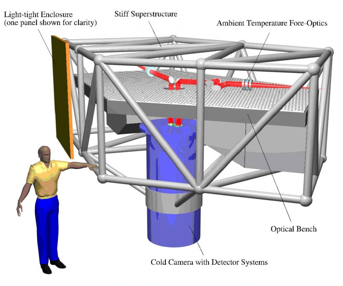
Figure 2: Simplified sketch of the interferometric camera LINC. The optical table which holds the ambient temperature fore-optics (collimator, lenses, wavefront sensors, active mirrors, etc.) is shown in the upper part of the image with a simplified version of the optical paths sketched in red. The cryogenic parts of the camera (science detector, fringe tracker, beam combiner, filter wheels, etc.) are located within the dewar (vertical blue cylinder) underneath the table. Only one of the light-tight panels (yellow) which cover the supporting superstructure (grey bars) is shown for clarity.
As can be seen in Fig. 2 the LINC system consists of four major components:
-
The cryogenic part of the camera. In Fig. 2 this part is shown as a blue cylinder symbolising the Dewar vessel. Within this Dewar are the reflecting beam-combining optics, the near-infrared science detector, the near-infrared fringe-tracker, near-infrared pupil and filter-wheels.
-
The ambient temperature optics. In Fig. 2 these components are shaded grey and are located above the Dewar ontop of the optical table. The two individual optical paths coming in from the two telescopes are shown in red.
-
The adaptive optics system for wavefront correction. Each optical path ontop the table incorporates three deformable mirrors for Multi Conjugate Adaptive Optics (MCAO). The respective wavefront sensors and frontend electronics are sketched as two grey boxes located on each side of the cryostat underneath the optical table.
-
The supporting stiff superstructure and lightshields. For simplicity only one panel of the light-tight cover of the superstructure is shown in Fig. 2. The superstructure provides a stiff internal reference frame for the individual camera components.
The I. Physics Institute of the University of Cologne is contributing to LINC in several ways. Based on the funds of two successful HBFG applications (Hochschulbauförderungsgesetz - a German fund to support participation in large instrumentation projects) and a successful application for Verbundforschung (a German fund to support collaborative projects of two or more research institutes) the Institute at Cologne takes responsibility for:
-
the technical concept, the provision and the operation of the cryostat,
- the design, construction and operation of the near-infrared imaging fringe-tracker for online correction of atmospherical pistonic aberrations,
- the simulation and development of a closed-loop numerical correction algorithm for piston correction, and
- the development and operation of cryogenic remote controlled positioning devices.
Except for the camera Dewar, which will be manufactured by commercial companies according to detailed technical specifications of the LINC team, the complex mechanical components will be manufactured at the mechanical workshop of the I. Physics Institute.