SMART SubMillimeter Array Receiver for Two Frequencies (490/810GHz)
Introduction
Modern heterodyne receivers in the submillimeter spectral range (wavelength between 0.3 mm and 1 mm; frequency between 300 GHz and 1000 GHz) have reached sensitivities close to their physical limit - the so called quantum limit. In order to make astronomical observing more efficient (i.e. gathering more data per unit of time) we and other groups (IRAM, MRAO, MPIfR, SORAL) have started to build array receivers. In contrast to the traditional single pixel receivers, array receivers not only observe one position in the sky but several positions simultaneously. Due to the difficult technology, submillimeter arrays have a relatively modest number of pixels, typically between 4 and 16.
At KOSMA we have built SMART (SubMillimeter Array Receiver for Two Frequencies), an array receiver with 8 spatial pixels aligned in two rows of four pixels (as of Sept. 2001, only one of the two rows is installed). In addition, SMART offers the unique feature that it measures two frequencies at the same time at each pixel. Each spatial position of the source is observed simultaneously at 490 GHz and at 810 GHz.
General Description
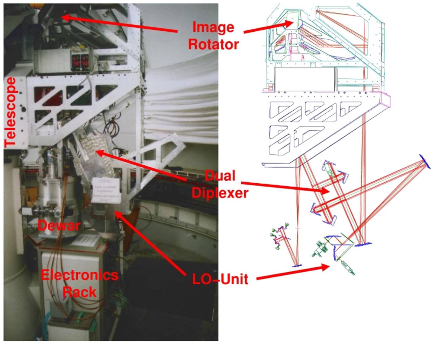
Figure 1 shows the instrument as it is mounted at the KOSMA 3m telescope on Gornergrat near Zermatt in Switzerland. The receiver consists of four major units:
- The image rotator. As the source is followed on its path through the sky during a long observation, its image in the focal plane of the telescope rotates. This effect, which is caused by the way our telescope is mounted (alt-az), is compensated by the image rotator.
- The main optics unit. this part contains most of the optics of the instrument, in particular the
- diplexer assembly, consisting of two identical Martin-Puplett-interferometers, and the
- local oscillator (LO) assembly, consisting of two solid state LO-chains and two collimating Fourier gratings as beam multipexers.
- The cryostat. Inside the cryostat, the detectors (SIS-mixers) and the first low-noise amplifiers are cooled to approximately 4 K using a closed cycle refrigerator.
- The electronics rack. This rack contains most of the control hardware required to operate the receiver together with a computer that monitors and controls the hardware.
Image Rotator
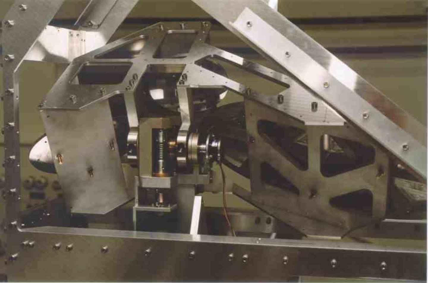

The image rotator allows us to reorient the image produced by the telescope. Since the telescope's axis of motion is not parallel to the earth's rotation axis, the optical image of an object seen through the telescope rotates while the telescope follows the object on its path through the sky. This rotation can be compensated by the arrangement shown in Figure 2.
Three plane mirrors are mounted in a K-configuration on a rotating unit. Rotating this unit by a certain angle rotates the image passing through it by twice that angle. The setup is mounted on on two ball bearings. It is driven with a double worm gear (two worms acting on one worm wheel) to ensure backlash-free movement. An angular position encoder measures the orientation of the image rotator. The instrument control computer updates the image rotator positions at regular intervals to keep the orientation of the astronomical object constant with respect to the detector array. The compact drive assembly with the bearing blocks, one worm and the angular encoder are shown in Figure 3.
Optics outside the cryostat

Two Gaussian telescopes make up the imaging part of the instrument optics. The first one magnifies the telescope's focal plane by a factor of approximately 2.5 to an image at the optical center of the diplexer unit. The second Gaussian telescope demagnifies this image again to the mixer units inside the cryostat. In order to minimize the size of the entrance window to the cryostat, the window has been placed between the two mirrors making up the second Gaussian telescope at an image of the KOSMA telescope's primary mirror. The reflection angles of the imaging mirrors are small (24° to 32°) and their focal length are large (300 mm to 1900 mm) to maximize the image quality.
The diplexer unit consists of two identical Martin-Puplett interferometers (Figure 4). They are used to combine the local oscillator signals with the sky signals. Since the two measurement frequencies require independent interferometers, the signals are split by a polarizer grid at the entrance and recombined in the same way at the exit of the diplexer unit.
Our relatively complex setup contains 14 warm optical surfaces in the signal path between the dewar and the telescope. This may seem to cause a substantial sensitivity loss because of residual absorption and scattering at these surfaces. However, we find that in the installed system's performance this effect is not significant.
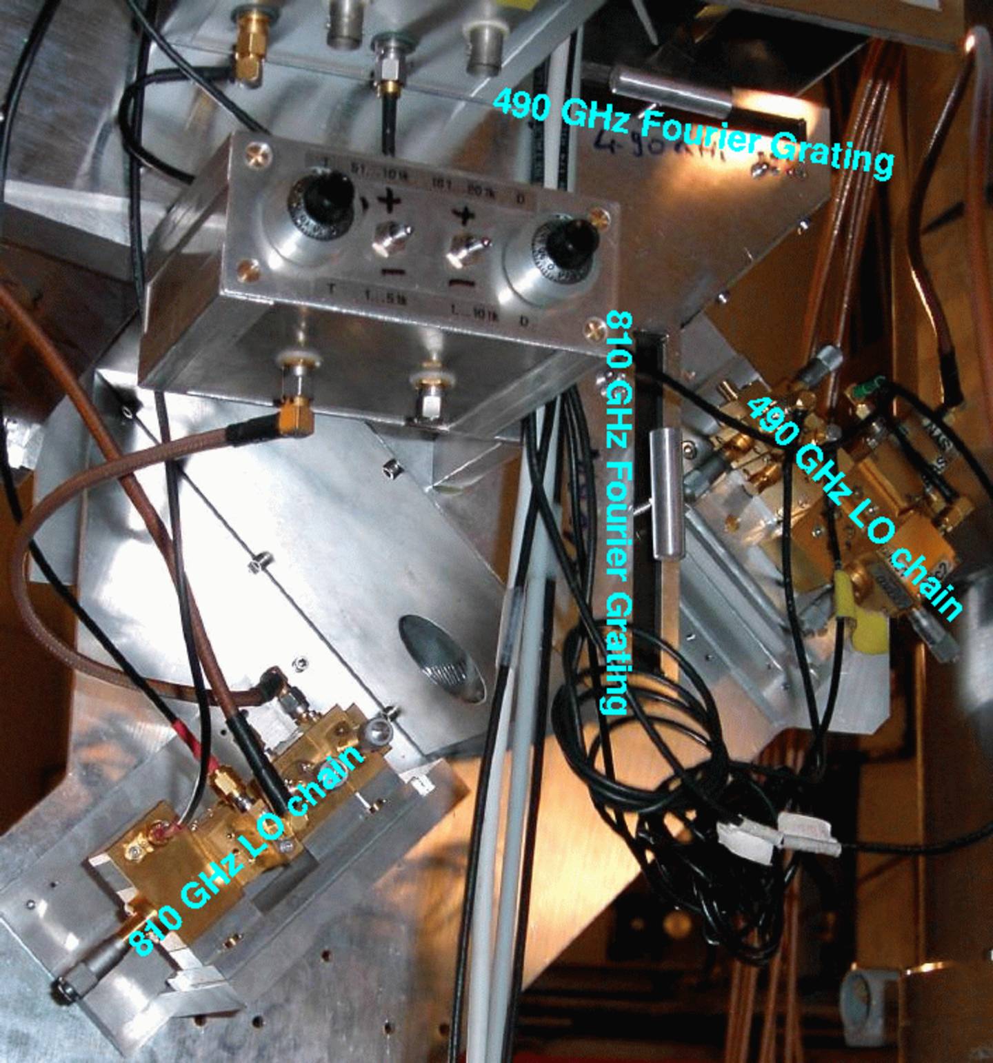
The local oscillators are phaselocked Gunn diode oscillators followed by frequency multipliers (Figure 5). The total multiplication factor for the 490 GHz LO is 6, for 810 GHz it is 9. The LO tuning bandwidths are approximately 455 to 495 GHz an 795 to 880 GHz, respectively. This also sets the useable frequency range of the receiver.
Each of the two local oscillator beams is split into 8 identical beams in a 2×4 arrangement matching the arrangement of the detectors. Splitting of the beam is done by collimating Fourier gratings. The useful bandwidth of the Fourier gratings is smaller than the receiver tuning range. Therefore, the gratings are designed to be easily exchanged. In Figure 5 the handles to pull out the gratings can be seen. A polarizer grid combines the 490 GHz beams and the 810 GHz beams, and an ellipsoidal mirror reimages them to match the signal beams, before they are injected into the diplexer unit.
Cryostat and cold optics
The receiver cryostat is very compact and it is mounted as closely as possible to the telescope pedestal in order to minimize the mechanical loading of the telescope's azimuth bearing. Cooling inside the dewar is provided by a closed cycle refrigerator (Sumitomo SRDK-415).
All the components inside the cryostat are suspended with fiber reinforced plastic straps from the top plate of the cylindrical vacuum vessel. The top plate is also the only mounting interface to the telescope. This construction provides for a good serviceability of the instrument. The dewar can be opened and the components inside can be accessed without removing the cryostat from the instrument. Therefore, the receiver does not have to be realigned after servicing the dewar components.
The optical setup inside the cryostat (Figure 6) is built as a compact assembly from precisely machined componants without any optical alignment. The optical surfaces of the components and their mounting reference planes are cut in a single machining cycle on a computer numerically controlled (CNC) milling machine to such high accuracy that no optical alignment is required after assembling the parts.
The main components in the assembly are two mixer units, one for each observing frequency, carrying up to 8 mixers, each. Together with a polarizer grid and an imaging mirror, the mixer units are sandwiched between two identical CNC-machined plates. This arrangement ensures an accurate relative positioning of all relevant optical surfaces within the cryostat. This assembly defines the relative alignment between the pixels of the array receiver. The optics outside the dewar - with the exception of the diplexer - is common to all receiver channels and does not significantly affect the relative alignment between pixels. Since optical alignment is neither required nor possible within the cold optics assembly inside the cryostat, this means that only the cryostat as a whole has to be aligned relative to the outside optics, and the optical alignment is as easily done as it is for a single pixel receiver.
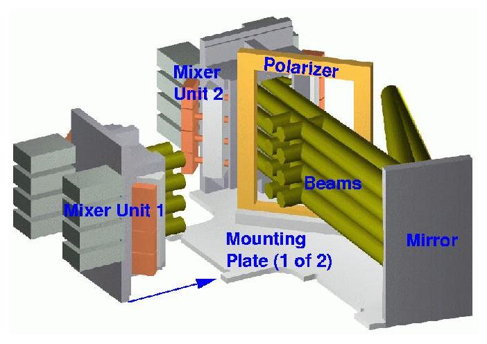
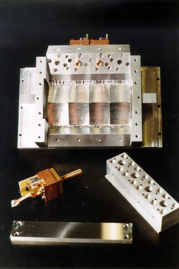
The mixer units (Figure 7) are integrated optics units, which contain 8 mixers, the collimating mirrors for the 8 beams, and the low-noise HEMT-preamplifiers for the IF signals. In order to achieve the best possible alignment accuracy, these units have been machined quasi-monolithically in such a way, that the mirror surfaces and the mounting surfaces for the mixer blocks were cut in a single machining cycle. The mixers are held by their horn antennas, which are inserted into precisely reamed holes in the mixer unit. Through this mounting scheme we make sure that the feed horns are aligned well with the optics, independent of the mechanical alignment between the horn and the mixer block.
The main block of the mixer unit carries a facetted mirror to collimate the mixer beams. In order to make the unit more compact, the beam path between the mixer and the collimating mirror has been folded, using a planar mirror. The mixers are mounted in a block holding four mixers. Figure 8 shows a photograph of the mixer unit parts.
The detectors are Nb-SIS waveguide mixers at 490 GHz and similar NbAl-SIS waveguide mixers in the 810 GHz branch. They were developed and built by the KOSMA mixer and detector group.
Electronics
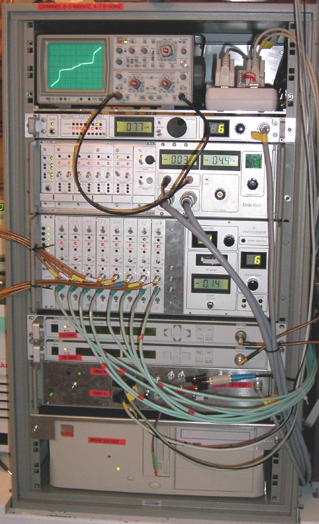
The receiver control electronics (Figure 9) is located in an electronics rack underneath the cryostat and the optics. From top to bottom the rack contains an oscilloscope to visualize IV-curves, the magnet supply box, the mixer bias box, the IF box, two microwave synthesizers, the computer interface box and the instrument control PC.
The magnet supply box, the mixer bias box and the IF box, each supply eight receiver channels each. They have eight identical control cards - one per channel - plus a control unit that selects the channel and displays and modifies the operations parameters of the selected channel. In order to improve the user interface and to avoid confusion, these boxes are linked through an address bus, which makes sure that all the boxes always select the same receiver channel. In this way at any time the user always gets the information of only one channel and also only can tune this channel on all the different boxes.
Through the interface box the control PC is linked with the address bus and the various electronics boxes. The PC monitors the system, and can also change the tuning parameters. The user thus can tune the system manually at the electronics rack or he can do it remotely through the computer. We also implemented an algorithm to tune the receiver automatically. In this mode the PC scans through all the receiver channels, determines their operating conditions and retunes the control parameters for optimum performance. For a system with many frontend channels, automatic tuning significantly improves the observing efficiency. Since the control PC runs under the LINUX operating system, it can easily be operated remotely.
The two microwave synthesizers in the rack are required for the phase lock loop of the two LO-Gunn oscillators. The PLL electronics is located near the oscillators in a separate small box. The PLLs and the synthesizers are also controlled either manually or by the PC through serial line connections.
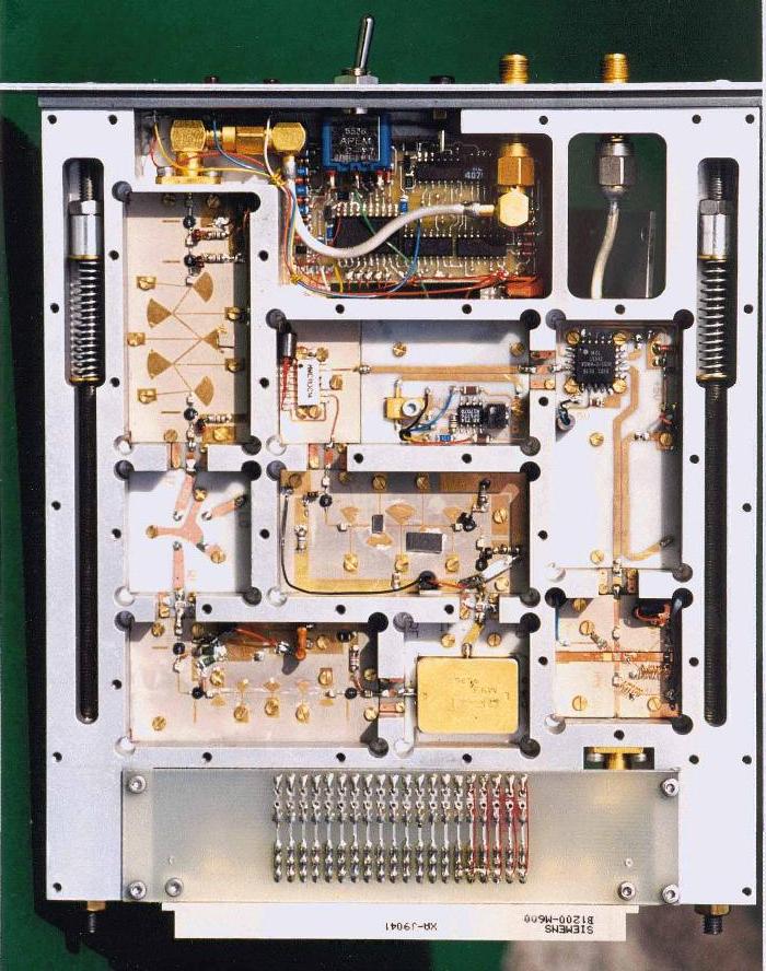
The IF processor unit is the link between the receiver frontend and the backend spectrometer. The latter, in our case is a set of array acousto optical spectrometers. For each receiver channel, the IF box has to perform a large number of tasks. In addition to filtering and amplifying the IF signal produced by the SIS mixers, it also contains two mixing steps to shift the frequency into the input band of the backend, it measures the signal power, and sets the output power level to the value needed by the backends. To calibrate the backend's frequency response and dark current, the IF box also provides a frequency comb and it contains a microwave switch to switch off the signal.
Figure 10 shows the layout of a one channel IF chain. It is built using commercial drop-in HF-components on microstrip boards to save space in comparison to connectorized components. We can fit the complete IF processing for 8 receiver channels in one 4HU 19'' rack mount box.
Performance

Figure 11 shows an antenna beam pattern measured near the receiver focal plane. The beam sizes and locations agree well with the design values, showing that the integrated optics design approach works well. The slight misalignment between the 490 GHz beams (red contours) and the 810 GHz beams (black contours) in the right hand part of the plot arises from a residual alignment error in the diplexer unit.
In Figure 12 and Figure 13 we show a receiver noise temperature measurement made with the complete system at the telescope using the telescope's calibration unit. The data are plotted against the spectrometer channel number. Channels are approximately 1 MHz wide. The most prominent feature in the measurement is the curvature across the IF-band, which is caused by the transmission function of the Martin-Puplett diplexer. If we assume an intrinsically flat receiver noise temperature (120 K at 490 GHz and 450 K at 810 GHz), and add the effect of the diplexer transmission to it, we get the black dotted curves in the plots, which represent the measured data fairly well.
Thus, the measurement shows that the typical receiver noise temperature at 490 GHz is around 150 K (mixer 3 has a known problem and will be exchanged); at 810 GHz it is around 500 K to 700 K. We should note that at 810 GHz the receiver noise temperatures measured in the array dewar are identical to the ones measured in a single pixel test receiver in the lab. This shows that our optical setup does not add a significant amount of noise, although the signal has to pass so many warm optical surfaces.