Hot Electron Bolometer (HEB) Mixers
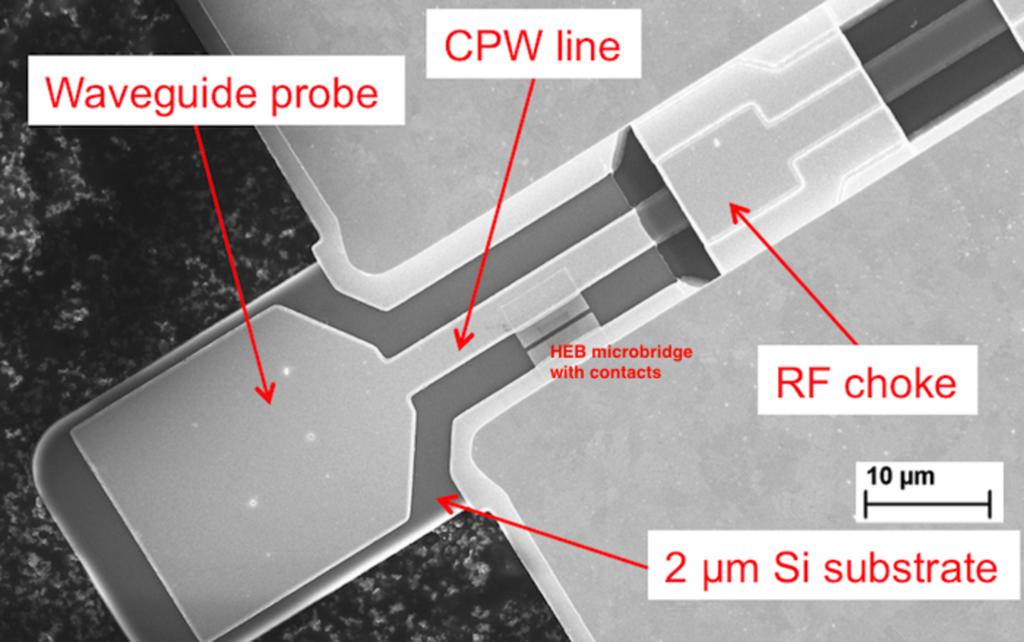
Fig. (1) Electron micrograph of a 1.9 THz waveguide HEB device developed for upGREAT. From left to right: Waveguide probe antenna on 2 µm Si membrane, transmission line, HEB microbridge in narrow gap near the image center, tuning capacitor, outside shows beamleads that suspend the device in the waveguide housing and also serve as DC and RF ground contacts.
In the early 90s a new frequency mixer device for heterodyne detection was introduced based on the very fast bolometric response times achieved when heating electrons in nanometer thin superconducting microbridges. For an introduction on these hot electron bolometer (HEB) devices, e.g. refer to these recent review papers for an introduction Klapwijk et al., IEEE Trans. on THz Sci. and Techn., 7(6):627–648, Nov 2017, and Shurakov et al., Supercond. Sci. Technol. 29 (2016) 023001. The HEB mixers rely on the non-linear resistance-temperature dependence of a superconducting material microbridge near its superconducting phase transition at critical temperature Tc. Bolometer based mixers do not follow the signal and local oscillator (LO) electrical field instantaneously (as is the case for SIS mixers), but rather react to the square of the sum of the fields. An intermediate frequency (IF) signal (3 magnitudes lower in frequency for THz receivers) is thus generated by the beat frequency between signal and local oscillator. The full spectral information is contained in the IF signal, which subsequently is amplified and spectrally decomposed by the receiver chain and spectrometer.
A HEB device is a superconducting material microbridge with typical dimensions of a few µm width, few hundred nm length and only several nm thickness. To enable sufficiently fast bolometric response (resulting to high enough receiver IF of a few GHz), only the electron bath must be heated above the lattice temperature creating the "hot electrons". This occurs if the strip is nanometer thin. For the most common phonon-cooled type of HEB device, typically made of the superconductor niobium nitride (NbN), and also at the center of our mixer development, the microbridge must facilitate a fast electron-phonon interaction to enable cooling of the electrons via the lattice phonons. Subsequently a fast phonon escape into the substrate, which serves as a heat sink, is required. A good lattice match between microbridge and substrate must be ensured in order to cool the microbridge on short enough time scales for the receiver application.
HEB mixers are presently the lowest noise (most sensitive) mixers at frequencies > 1 THz where SIS mixers cease to work due to their fundamental operation limit determined by the superconducting electrode's gap frequency. Semiconductor Schottky diode mixers are still significantly more noisy. For our THz astronomy heterodyne receiver applications within the research framework of our institute we therefore need HEB mixers.
Current HEB mixer research
Our current research in improving the performance of our HEB mixers through gaining a deeper understanding of the underlying device physics, new materials development, integration of on-chip RF balancing circuitry and developing hardware for a 11 THz mixer is summarized on this page.
Development in Cologne
We have researched HEB mixer development for application in radioastronomical Terahertz receivers since the mid 90s, starting with the diffusion-cooled sister (cooling of the hot electrons mostly via the normal conducting contacts) to aforementioned principle (Fiegle et. al, IEEE Trans. Appl. Supercon., 7(2):3552–3555, June 1997). From the beginning we choose to develop mixer technology based on waveguide feedhorn radiation coupling rather than the more common and more easily frequency-scaleable dielectric lens based systems. In our reasoning this ensures a better defined beam pattern, which is crucial for efficient radiation coupling of the mixer through a complicated telescope system at an observatory. A well-defined input beam into the mixer translates to well-defined beam on the sky, which is mandatory for e.g. mapping applications.
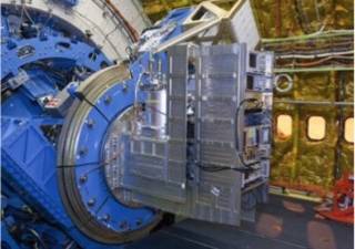
Fig.2 The GREAT modular receiver platform installed on the instrument flange of the telescope inside the SOFIA aircraft.

Fig. 3 SOFIA observatory in flight with door to telescope opened in the rear of the aircraft (© NASA).
Our main observatory platform for THz HEB mixer development is the modular GREAT (German REceiver for Astronomy at Terahertz frequencies) heterodyne instrument for SOFIA (Stratospheric Observatory for Infrared Astronomy), with the Cologne groups (instrumentation, software and astrophysics) having a very strong contribution to the German consortium that develops and operates the instrument (Figs. 2 and 3). We develop, implement and operate all HEB mixers in the THz channels of the receivers, i.e. currently 1.4 THz (L1), 1.9 THz (L2 and LFA), 2.5 THz (M) and 4.7 THz (H and HFA), with first light on SOFIA being in 2011.
For the initial set of single-pixel GREAT channels we have achieved equivalent receiver noise temperatures (DSB) of 500 K at 1.5 THz, 900 K at 1.9 THz, 900 K at 2.7 THz, and 800 K at 4.7 THz. Recently we have implemented the first THz heterodyne focal plane arrays (multi-pixel receivers) that are in continuous astronomical operation.
HEB mixers for THz heterodyne focal plane arrays
Focus of our current HEB mixer development lies on the two "up"GREAT focal plane array extensions to GREAT. In order to improve the overall efficiency of an astronomical heterodyne receiver besides, naturally, using the most sensitive mixers available, the way to go is to incorporate more pixels into the receiver front end. In stark contrast to everyday used commercially developed semiconductor technology such as digital cameras with millions of CMOS or CCD type detectors, the heterodyne receivers in radioastronomy use very few pixels due to that fact the superconducting detector technology is less mature. Also keep in mind that each heterodyne mixer pixel needs a local oscillator source!
At Terahertz frequencies only in the last 10 years there has been significant momentum to implement focal plane array type receivers, i.e. receivers with several spatial pixel. It is important to understand that with these comparebly few spatial pixels a wealth of science can be done, as the heterodyne system multiplexes each spatial pixel into many thousand spectroscopic frequency "pixels" (i.e. channels) covering the receiver IF range. Only with such a very high spectral resolution, typically R=1E7, interstellar molecular and atomic species, their physical state incl. their line-of-sight velocity components (Doppler shift) can unambiguously be identified. After the pioneering observational efforts in radioastronomy, moving into the THz frequency range e.g. with the Herschel Space Telescope, SOFIA's predecessor Kuiper Airborne Observatory as well as SOFIA itself, astronomers worldwide are seeking to gain a better larger scale overview of the astronomical objects of interest, e.g. large star formation regions. For this instruments with efficient mapping capabilities are needed, which motivates our "up"GREAT receiver extensions at 1.9 THz and 4.7 THz.
1.9 THz waveguide HEB mixers for the upGREAT Low Frequency Array
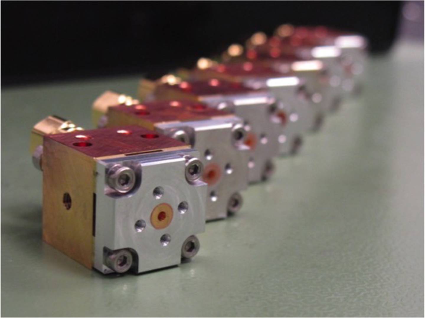
Fig. (4) Seven fully assembled and qualified mixer units prior to delivery for receiver integration at the MPIfR. These 1.9 - 2.5 THz mixers populate one of two polarisation diplexed sub-arrays in the upGREAT Low Frequency Array receiver.
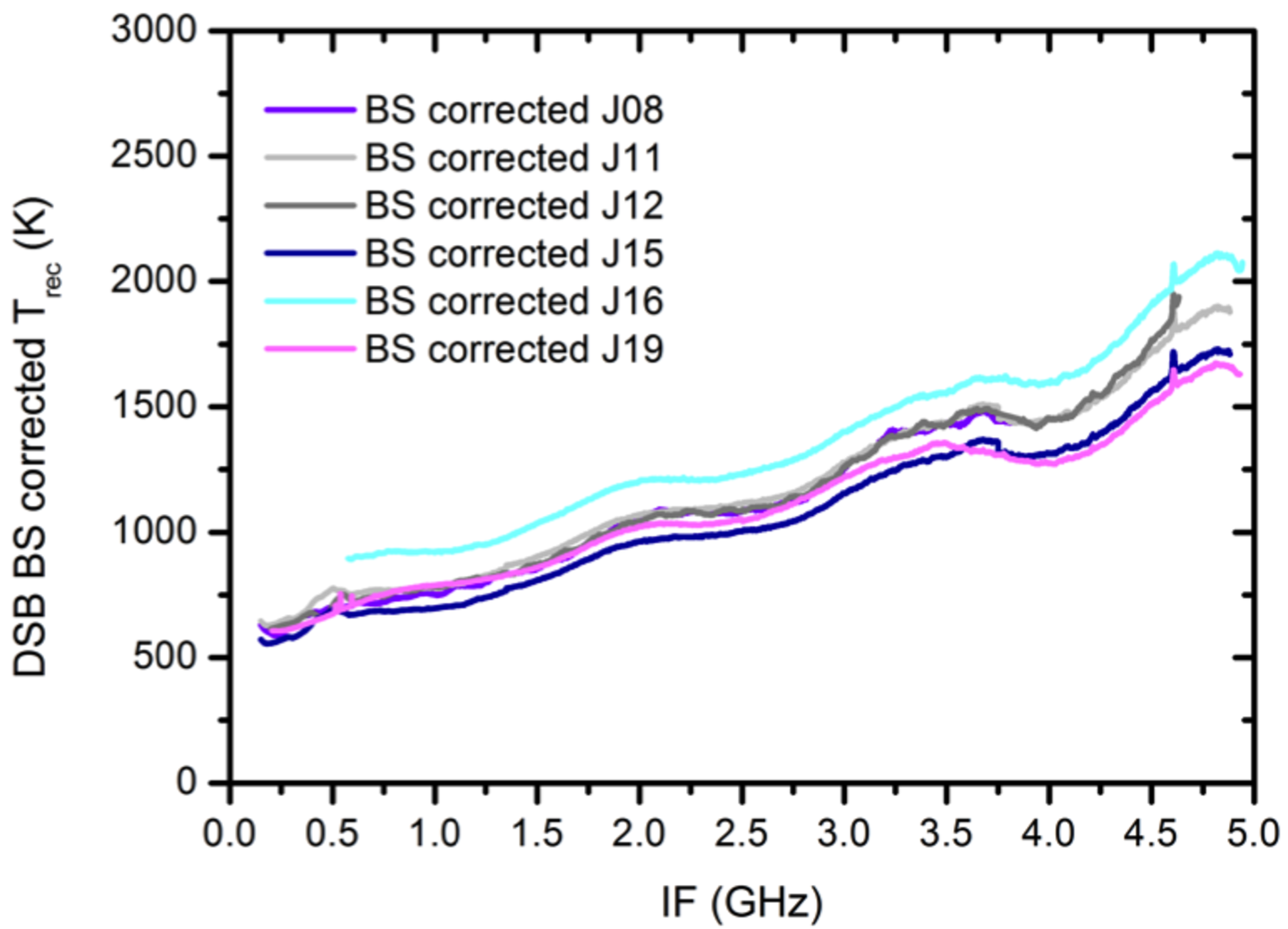
Fig. (5) Trec(IF) lab test data of the seven mixers delivered for sub array #1 of the upGREAT LFA receiver. The Trec data is corrected for beamsplitter transmission because different signal coupling factors were used.
Development of upGREAT LFA mixers
We have developed mixers for the 2x 7-pixel subarrays that the low frequency array (LFA) is comprised of. The mixers are designed with an large input bandwidth 1.8 - 2.5 THz, which e.g. includes the important C+ fine structure transition at 1900 GHz. The mixer hardware was matured to ensure compatibility to the array application, mainly reference stops to ensure a ± 10 µm lateral alignment accuracy of the optical (feedhorn) axis. Fig. 1 shows a close-up of the front RF structures of such a HEB device. For effective array operation devices with low (< 1 µW) and reproducible local oscillator pump power are required, whilst retaining the excellent noise performance of the single pixel receiver. Uniformity of device characteristics is critical for array mixer device fabrication (Figs. 5-7). We delivered all 14 mixers plus replacements for commissioning of the LFA in 2015. The commissioning of the receiver was highly successful and since early 2016 the LFA is fully commissioned and in regular science operation, e.g. during the SOFIA flights from New Zealand for observations of southern hemisphere objects. The upGREAT LFA is the first functional array receiver at 1.9 THz and the gain in mapping speed experienced during commissioning fully confirms the necessity for focal plane arrays. For the time being the upGREAT LFA is the only astronomical heterodyne receiver in operation at 1.9 THz.
A description of the development work incl. our mixers of the LFA receiver is found in Risacher et al. IEEE Trans. on THz Sci. and Techn., 6(2):199–211, Mar 2016. For the outstanding contribution of the upGREAT team to advancement of THz technology the 2018 THz Science and Tech. Best Paper Award of the IEEE Microwave Theory and Techniques Society (MTT-S) was awarded to this publication. A detailed summary of the science from the first light observations is found in Risacher et al., Astronomy and Astrophysics, 595:A34, 2016.
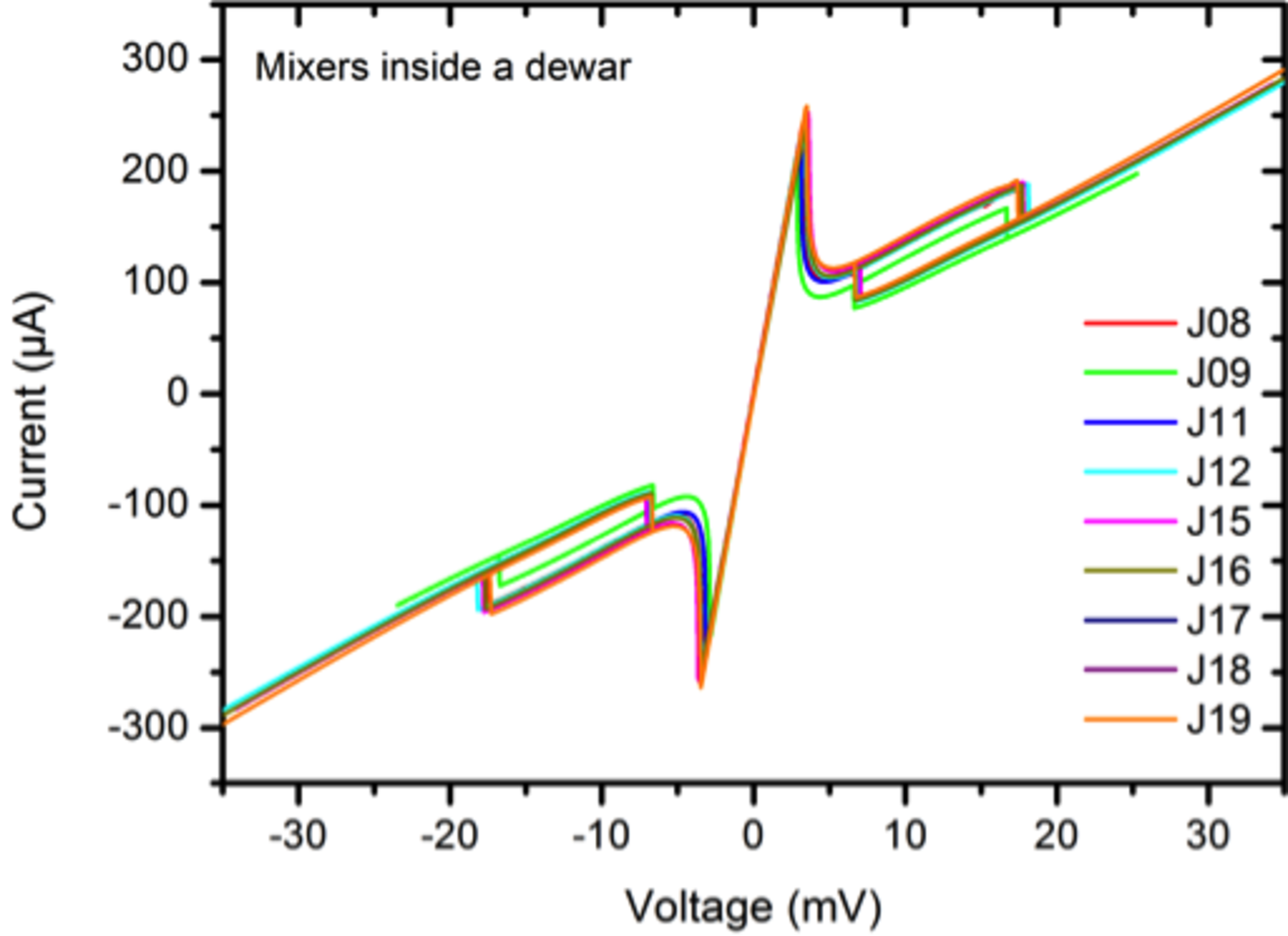
Fig. (6) DC IV curves of one batch of HEB devices fabricated for the upGREAT V array.

Fig. (7) DC RT curves of one batch of HEB devices fabricated for the upGREAT V array.
4.7 THz waveguide HEB mixers for the upGREAT High Frequency Array
Observation of the [OI] fine structure transition at 4745 GHz
Besides the [CII] fine structure transition of the ionized carbon atom the (3P1-3P2) fine structure transition of atomic oxygen ([OI]) at the frequency of 4.74477749(16) THz (63 µm, see CDMS), of atomic oxygen is another major "cooling lines" of the interstellar medium (ISM). The phrasing "cooling line" describes that this one transition by itself contributes significantly to the overall radiation budget of e.g. star formation regions in the ISM. Thus a lot of information can be gathered through high spectral resolution observations of this line. The [OI] transition has hardly been observed with sufficient spectroscopic resolution due to the fact that it can only be detected from an airborne or space observatory due to the water vapor absorption in the atmosphere. Prior to our SOFIA observations the only high resolution spectra obtained were with the Kuiper Airborne Observatory (KAO), the predecessor of SOFIA, with a Schottky diode mixer (Boreiko and Betz, ApJ, 464, pp. L83, 1996). With the appearance of much more sensitive superconducting HEB mixers at THz frequencies, and our long-standing expertise gained with lower THz frequencies HEB mixers, it was obvious to develop 4.7 THz HEB mixers for a new receiver channel on GREAT/SOFIA. At first the single pixel GREAT H receiver system was developed in 2014, serving as a prototype for the upGREAT High Frequency Array (HFA) 7-pixel receiver in 2016.
Prototype mixer development for GREAT H channel
In December 2013 the development of our first 4.7 THz waveguide superconducting hot-electron bolometer (HEB) mixer was completed. The 5.5 nm thickness x 300 nm length x 3600 nm width NbN microbridge is integrated into a Au normal-metal planar circuit on a 2 µm thin silicon substrate. As with all other mixers the NbN thin film, the device circuitry and the mixer block were designed, developed and fabricated in house in our microfabrication lab and in our fine mechanics workshop. We use a CuTe alloy as a material for blocks because it has a higher hardness than pure Cu to avoid burrs which are a critical issue given the small dimensions of the structures. The 24 µm x 48 µm (22 µm depth) waveguide and the 16 µm x 105 µm (4 µm depth) substrate channel are stamped into the block with the required precision of ± 1 µm (Fig. 10). This was made only possible with the highly specialised and qualified personnel in our machine shop using a Kern Nano™ sub-micrometer precise CNC milling tool. The 4.7 THz feedhorn, as with all other feedhorns we use for our HEB mixers, is developed and manufactured through mandrel electro-forming by Radiometer Physics GmbH according to our optics specs. The design features a smooth-walled spline profile, a tapered transition to the rectangular waveguide and waveguide output. The fabrication of the horns is very resource intensive and we are express our gratitude towards RPG for the cooperation.
The device is adjusted on the waveguide with a hexapod nano manipulator and is ultrasonically bonded to the block (see Fig. 8). The measured mixer direct detection response is in a good agreement with the 3D EM circuit simulation over the design RF bandwidth.
In May 2014 the GREAT "H" High-frequency-channel with one of our 4.7 THz mixers had "first light" on SOFIA. The flight campaign was a huge success, yielding more high-resolution [OI] spectra than were ever taken before. The GREAT H receiver demonstrated a sensitivity several magnitudes higher than the spectrometer used by Boreiko&Betz. Below is an example of the data taken during this early campaign (Figs. 8 and 9). The GREAT H channel was the first receiver to employ HEB mixers for astronomical observations at these frequencies and our development of unique waveguide technology at 4.7 THz has attracted a lot of attention in the community.
Our development effort for the 4.7 THz waveguide mixer is summarized in Büchel et al. IEEE Trans. on Terahertz Science and Technology, 5(2):207–214, March 2015.

Fig. (8) Color coded intensity map of the planetary nebula NGC 7027, a final stage of stellar evolution, in the [OI] line at 63 µm, taken on SOFIA in May 2014 with our 4.7 THz mixer. The grey circle represents the SOFIA telescope beam diameter at 63 µm wavelength.
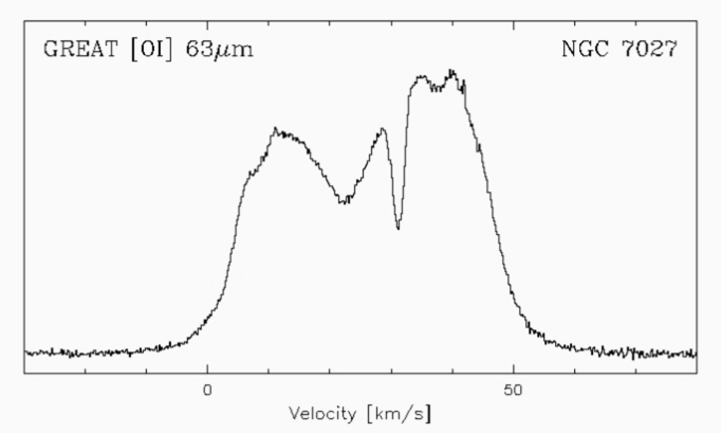
Fig. (9) A single spectrum of the map of NGC 7027 showing the complex velocity structure of the planetary nebula that is only visible in high-resolution heterodyne spectroscopy. The integration time was only 2 minutes. The excellent signal-to-noise ratio confirms the very high sensitivity of the HEB mixer and stability of the receiver. The narrow dip is the telluric [OI] line of the earth's upper atmosphere seen in absorption from the flight level at about 43000 feet. The expansion velocity of ± 25 km/s corresponds to 90000 km/h. TNT detonates with 9.6 km/s.
Development of upGREAT HFA mixers
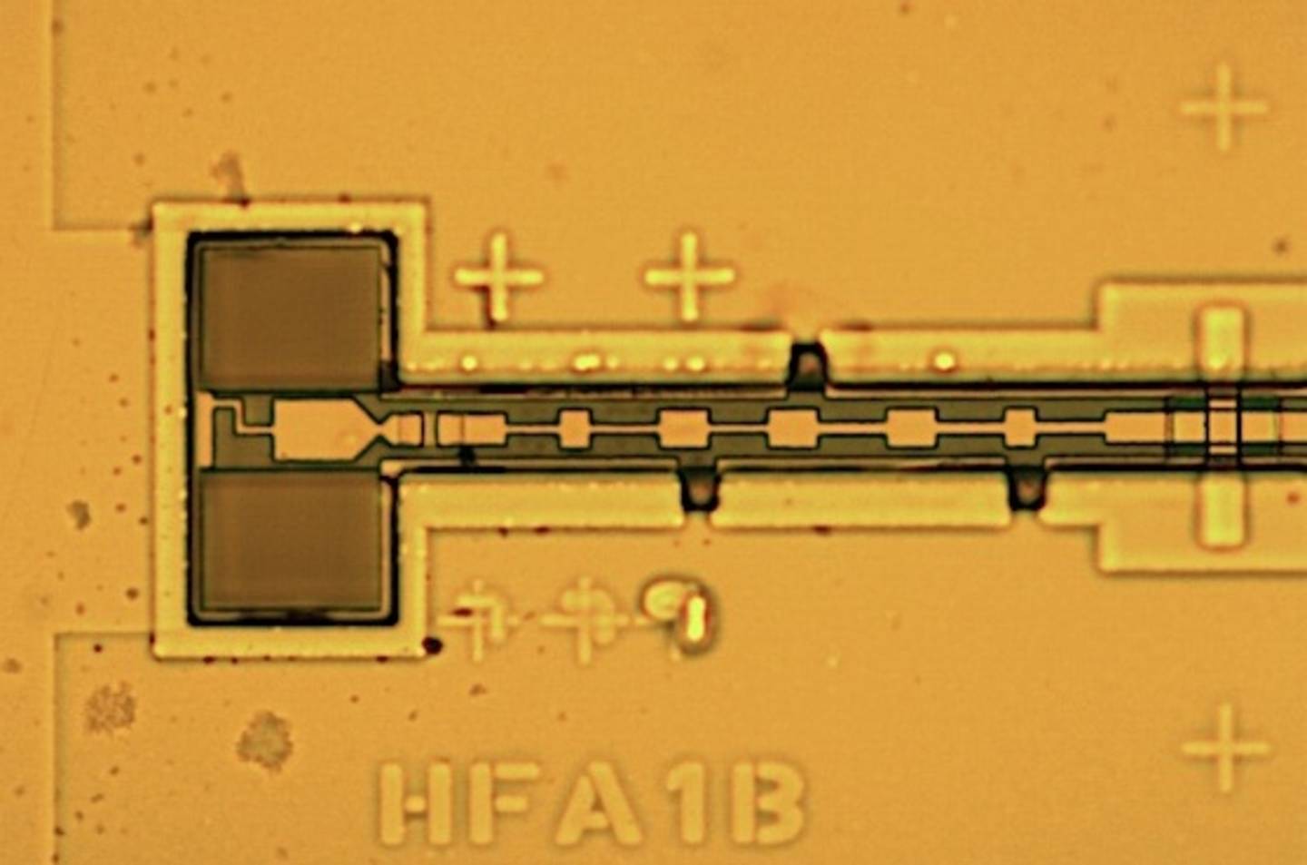
Fig. (10) Optical microscope image of the central part of a 4.7 THz HEB device. The waveguide opening to the left measures 24 µm x 48 µm. The Silicon substrate of the device (greyish horizontal strip at center) is only 2 µm thick.
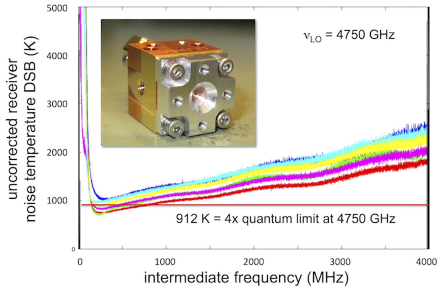
Fig. (11) Measured uncorrected double sideband receiver noise temperatures (Trec,DSB) vs. intermediate frequency for the HFA array measured at 4750 GHz. The inset shows one of the fully assembled mixer hardware units (footprint is 17 mm^2).
With successful development of the 4.7 THz HEB mixer for the GREAT H receiver and great success with the commissioning flights our baseline mixer design was verified and we could move into mass production for the 7-pixel upGREAT high frequency array (HFA). Commissioning of the HFA commenced in Oct 2016 with from the start excellent science return. The HFA has been in operation since. The upGREAT HFA is the only heterodyne array receiver in operation at 4.7 THz and for the time being will stay unique. For all flight mixers in the array the measured noise temperature (DSB) Trec vs. the intermediate frequency IF is shown in Fig. 11. The average 3 dB noise roll-off for the IF signal is 3.3 GHz.
Acknowledgement
Our HEB mixer development for GREAT and upGREAT was sponsored by the German Space Agency Deutschen Zentrum für Luft- und Raumfahrt e.V (DLR) with funds from the Federal Ministry of Economics and Technology according to a ruling of the Federal Parliament under support codes 50OK0801 and 50OK1103, and is carried out within the Collaborative Research Centre 956, sub-project D3, funded by the Deutsche Forschungsgemeinschaft (DFG).