current HF design
Sideband Separating Balanced Mixer Design
Currently we develop a sideband separating (2SB) balanced mixer for the frequency range from 430 to 500 GHz. The RF circuit of the 2SB balanced mixer consists of two quadrature hybrid type single balanced mixers which are combined with a third RF quadrature hybrid coupler for the incoming RF signal and with an in-phase Power divider on the LO radiation side. The four IF signals, one for each mixer, have to be combined with the right phase in two steps. First for the two balanced mixers with e.g. an IF Wilkinson combiner or 180 degree coupler to two DSB IF signals. Then, these two IF signals are superimposed to the final IF signal with an IF quadrature hybrid coupler, which eliminates either the noise of the upper sideband (USB) or the lower sideband (LSB) due to the additional 90 degree phase shift. In addition to the side band separation, the mixer retains the advantages of a balanced mixer in comparison to a single-ended mixer. The main advantage is that the LO AM noise will be reduced.

The mixer will be built in the same technology as the existing balanced mixer. The substrate will be a 9 µm thick SOI substrate. The RF circuitry will be made in Nb CPW technology with SiO2 dielectric supported bridges between the ground planes. An important feature for the on-chip 2SB balanced mixer is the NbN thin film load/resistor. The sheet resistances of 25 Ohm/square have been shown for films of 90 nm thickness down to 2.3 K. The thin film resistor is needed as a 50 Ohm load at the input hybrid and as a resistor 80 Ohm for the In-Phase Wilkinson Power Divider. The four SIS mixers will be integrated at the ports 2, 3, 5 and 6. The whole chip will be supported and contacted by gold beamleads.
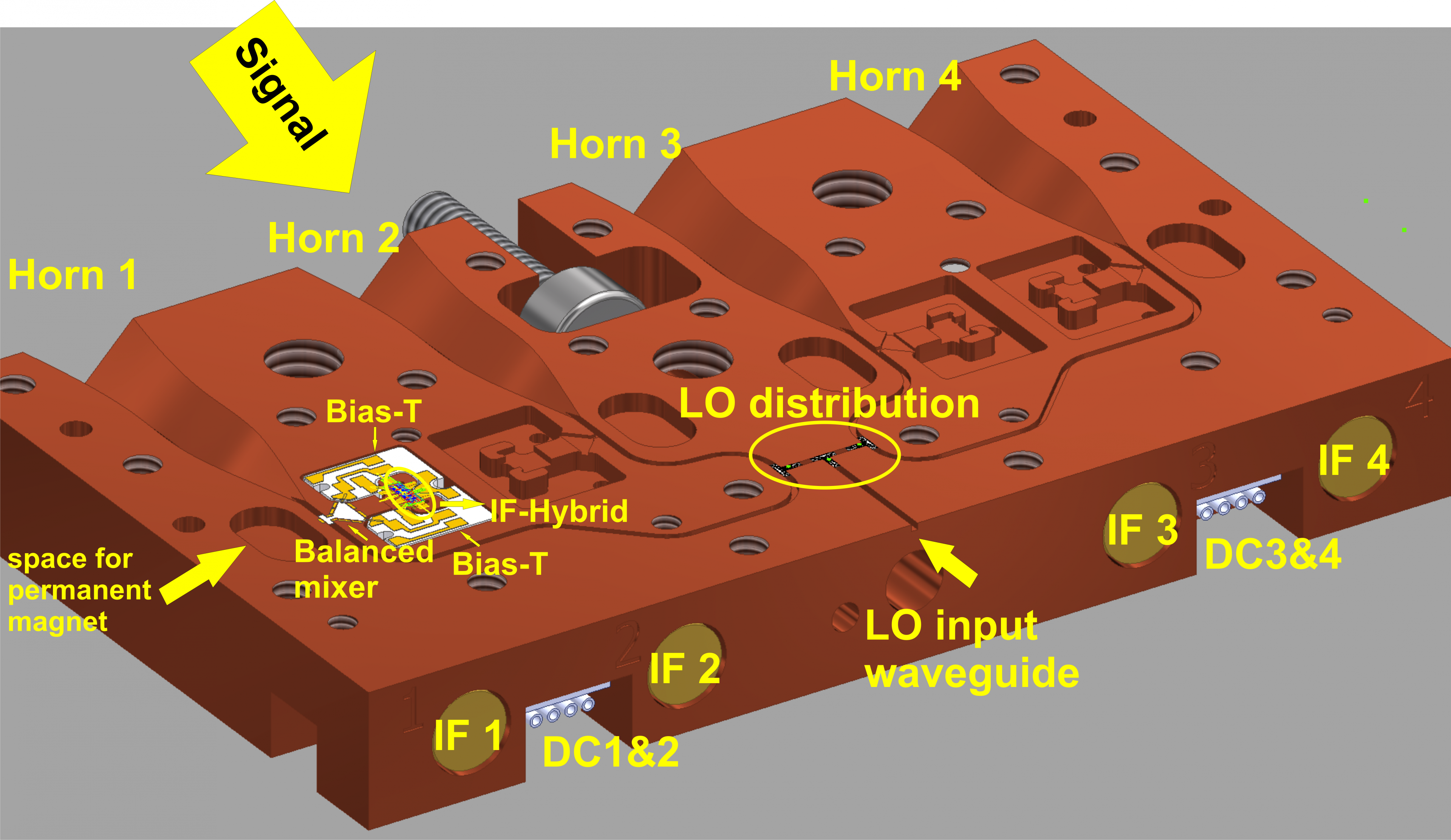
For the first measurements, we designed a prototype mixerblock - which includes the RF chip of the 2SB Balanced Mixer, the IF boards to the four G3PO connectors and the permanent magnets for suppressing the Josephson current. This block enables us to do the IF combination at first at room temperature to test predominantly the RF part of the circuit. In the future, the IF circuitry will be integrated in the block.

LO Distribution for CHAI
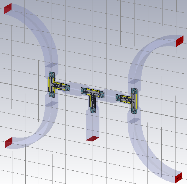
The CCAT-prime Heterodyne Array Instrument (CHAI) is a modular, dual-frequency band focal plane array receiver, which in the first-light configuration covers the scientifically most important parts of the 460 GHz (600µm , band L) and 830 GHz (370µm , band H) atmospheric windows for simultaneous observations with 64-pixel arrays each. In order to convey the LO signal to the 64 pixels of an array we conceived a modular approach for the distribution scheme. The complete array will be comprised of 2 by 8 blocks, each block containing 4 pixels in a row.
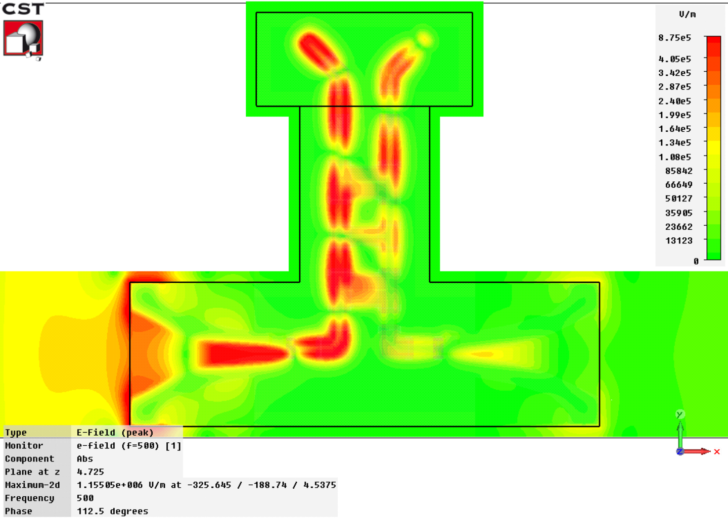
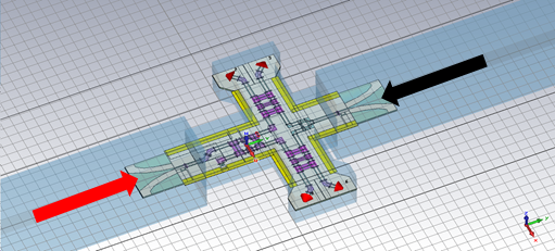
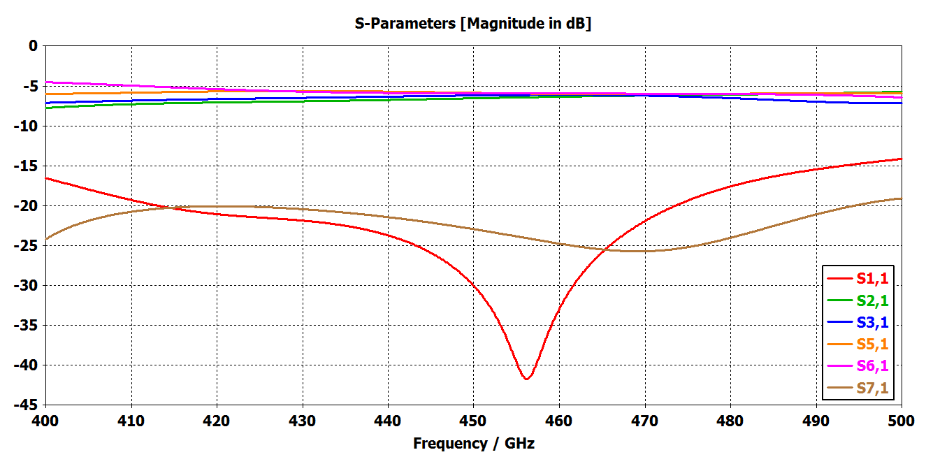
With this concept in mind, we design a basic one to four power division that will be part of the 4 pixel block based on 90 degree hybrids. We base the current device on a hybrid three branch model designed by Marc Westig and modified by Sina Widdig. The 90 degree hybrid is a four port device, it has an input port, two output ports and an isolated port, with the particularity that its outputs out of phase by 90 degree. Even though the isolated port is named isolated still receives a sligth amount of energy when the two output ports are matched. If the port it is not terminated in a load, the energy receibed would be reflected back to the output ports, generating a standing wave in the LO path that would cause instabilities in the LO bias of the mixers. We have two different posibilities in order to terminate the port, a on-chip load or to launch the signal to a waveguide and build a waveguide load. Due the complexity of building a waveguide load we opted to build a on-chip load made of a a thin (~25 nm) Titanium nitrate film, that remains normal conductive also at the operating temperature of the mixers (4.2K).
After the power division is carried out by the hybrid, the signal needs to be launched to waveguides for its further distribution to other hybrids or to be delivered to the mixers. To accomplish such deed we resort to waveguides, as they are easier to manufacture than CPW lines or planar circuits. There is also the concern about the handling of large silicon slabs, as they may break during the manufacturing process. The dimension of the waveguide proposed to deliver the signal are 230 µm × 460 µm.
The design is fabricated with the Cologne Silicon on Insulator (SOI) Process , resulting in a 9 um Silicon Slab with Niobium metallization and gold beamleads for contacting metallization layer.
At first the 4 pixel prototype block will be thoroughly tested, as a prototype. If the Lo distribution chips performs well they can also be used in the 1 to 8 LO power divider that will connect a stack of 8 4 pixel blocks on top of each other in the final array (Fig 1.a).

Acknowledgements
Balanced Side Band Separating Mixer Development and the CHAI mixer and LO-power distribution development are carried out within the Collaborative Research Centre 956, sub-project D3, funded by the Deutsche Forschungsgemeinschaft (DFG).