Superconducting Devices Testlab
In this lab we do all the testing, not only of devices but also of materials and high frequency circuits relevant for detector development. Many tasks in designing and building set-ups, be it mechanics, cryogenics, optics or data-acquisition are done by students, often as a team, ensuring a broad education not only in technical physics skills, but also in planning and communication.
For cryogenic device measurements we have 3 possible ways of cooling devices:
- a number of dipsticks for dedicated devices-evaluation in liquid helium. This is often the first test of a device fabricated in our cleanroom, and it is done in various stages of the fabrication. We have dedicated electronics for accurate measurements and all measurements are stored in a data-base to provide traceability and easy access for all members of the group.
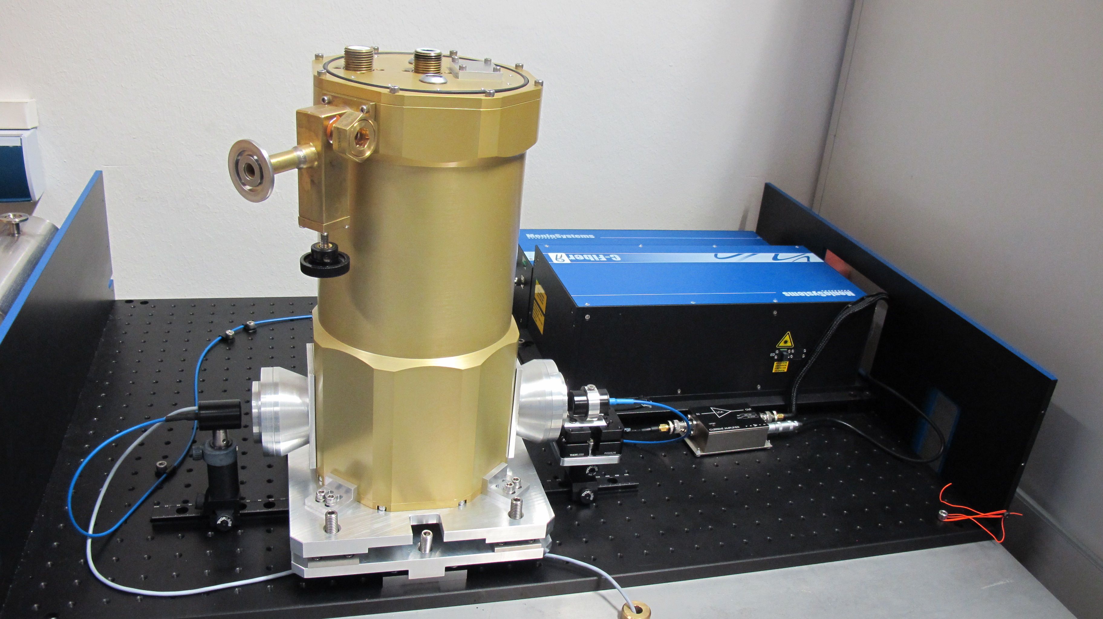
- Liquid helium dewars for measurements at 4.2K ( or by pumping on the liquid Helium down to 2.8 K) in vacuum ( see photo above). The detector housing is attached to the cold plate of the dewar, which is the outside of the bottom of the liquid helium tank. This is e.g. the way SIS mixers and HEB mixers are tested. The dewars are wired and fitted with windows in house, getting adapted to new measurements several times during their life-time. All test optics are all designed and fabricated in house, so that we have a well characterized set-up which is necessary to de-embed the device performance from that of the whole set-up. Our detectors hence are fully characterized and optimized for operation in a receiver at an observatory under real-life conditions.
- An Adiabatic Demagnetization Refrigerator ( ADR) for measurements down to 40 mK. The ADR does not use cryogens, but is pre-cooled until 3K by a pulse tube cooler, and then to 40 mK by the adiabatic demagnetization stage.The ADR is predominantly used for our MKID development, but also for materials parameter measurements.
For DC testing we employ dedicated electronics that is partly built or adapted in house to tailor it to our specifications. Examples are the resistance versus temperature measurement of the superconducting transition (Fig.7) of the HEB, using two commercial low noise lockin amplifier cards and some in house electronics and data acquisition to get accurte measurements. Or the read out electronincs of the ADR MKID set-up, where grounding, shielding and filtering have to be developed dedicated to the set-up to get reliable measurements.
At intermediate frequencies up to 12 GHz we acquire cryogenic low noise amplifiers commercially. Room temperature set-ups are built in house from commercial components. This includes e.g. a set-up to map a 5 GHz IF output of a mixer onto a 1,5 GHz wide digital Fourier Transform Spectrometer in 4 (slightly overlapping) steps.
For high frequency testing we distinguish between broadband characterization and heterodyne measurements.
For broad band spectroscopy we employ 2 instruments. A new, recently acquired, Bruker Fourier Transform Spectrometer (FTS) that can be used from 400 GHz-12 THz with different beam splitters. The FTS is indispensible for a quick broadband test of our heterodyne mixers, using the mixer as a direct detector in the FTS. Comparison of high frequency design with its practical realisation cannot be done very well without it. The FTS is also used for some material characterizations like anti reflection coatings using a commercial DTGS detector.
Our main material characterization, between 0.1 and 4 THz, is a Time Domain Spectrometer. This is a commercial system that we are step by step adapting to our needs. We use it to characterize materials (fabricated in our clean room) at THz frequencies. Frequency dependent losses, that are very relevant for sensitive detector development, are determined better with a TDS because both amplitude and phase of the transmitted (reflected) signal are measured.
For heterodyne experiments we have a number of coherent sources that we use as local oscillators. We have old Gunn oscillator sources at 460-490 GHz and 800-820 GHz. Further some synthesizer/power-amplifiers based sources at 310-360 GHz , around 1.1 THz and around 1.9 THz and a home-made QCL source around 4.7 THz. Optics and calibration loads are all designed in our group and are fabricated in our excellent in-house workshop.

