HF circuits
Because we develop detectors for astronomical observations, we need to do accurate high frequency design. Sources that are detected by heterodyne mixers have often very narrow band signals and ground based observations in addition are limited to atmospheric windows. For high frequency design we use the commercial packages like CST Microwave Studio for 3D, and SONNET for 2.5 D, augmented by in house developed software routines. High frequency properties of our thin films are implemented into these applications. To determine these properties we rely on a combination of measurements of DC properties, theory and also if possible on direct measurement with the TDS spectrometer. The in-house fabrication gives us easy access to test pieces. Often dedicated test structures fabricated are on the same wafer as the devices,to verify the actual layer properties.
With our E-beam lithography facility we are able to define very small structures, which is indispensible for the frequencies above 1 THz. We can also accurately place the multiple layers of a device on top of each other. This is especially important for the very high frequency structures and for the integrated tuning of the SIS junctions.
SIS integrated tuning circuits
SIS junctions are capable of quantum limited mixer performance, but to make this happen in a real receiver the signal coupling to the device needs to be near 100%. Since the Nb-AlOx-Nb junctions have a specific capacitance of approximately 85fF/µm2 and our smallest reliable junction areas are around 0.5µm2 some kind of microwave circuit needs to be in place to mitigate the influence of this capacitance on the signal coupling. There are many possibilities, depending on frequency, specified bandwidth, material choice, etc. In our laboratory we are using resonant tuning circuits, made of superconducting layers whenever this is possible.
For frequencies below the gap frequency of Nb the tuning circuit has Nb groundplane and Nb topwiring with a 200-300nm SiO2 dielectric. Above 700 GHz we use a NbTiN groundplanes with normalconducting ( Al) wiring. Between 700GHz and 800 GHz Nb wiring also still gives reasonable results.
Two well known examples of tuning circuits are shown in the drawing. The circuit with one junction consists of a small series inductance that compendates the capcitance, connecting the SIS junction to a 2 step quarter lambda transformer match to the antenna. The circuit is made in microstrip technology usually with a 200-300 nm SiO2 dielectric.
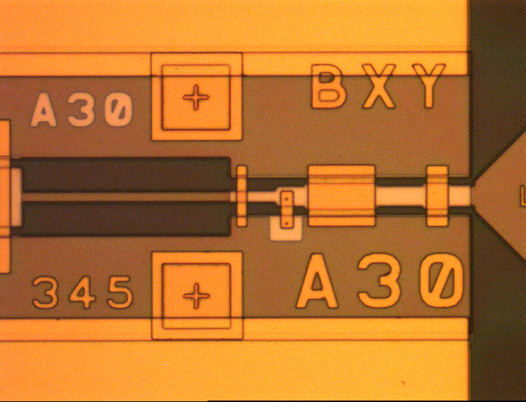
Examples of fabricated tuning circuits for 280-380 GHz are shown in the photos. The upper device employs 2 SIS junctions in series, the antenna (waveguide probe) is at the far right, and the tuning circuit consists of quasi lumped element capacitors (overlaps) and inductors (CPW lines). To the left is the RF blocking filter, reflecting the RF with te proper phase.
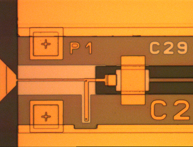
The lower structure employs 2 SIS junctions in parallel connected by a microstrip inductor and a quarter wavelength microstripline to match to the antenna on the far left, like the structure with 2 junctions in the drawing. To the right is again the RF blocking filter.
Both devices show a very similar noise temperature. If the mixer peformance is de-embedded from that of the whole set-up the noise is around 1.5 times the quantum limit.
At higher frequencies the tolerances in overlay accuracy and especially in the junction area definition are the main sources of inaccuracy comparing the measured performance with the design. Layer properties, especially when composite materials like NbTiN are used, are a second source of inaccuracy. Simulation of the high frequency structures seems to be fairly accurate judging by the comparison of design and measurement of HEB mixers, that do no need an elaborate integrated tuning because HEB's can be modelled as a resistor.
Planar SOI circuits
We are more and more exploring the possibilities of the use of SOI substrate technology for THz mixers. As a first project we have developed a balanced mixer at 460 GHz, with a 3dB 90° hybrid integrated on the same 9 µm Si substrate as 2 SIS mixers. The hybrid is made in Nb CPW technology with dielectric supported bridges between the ground planes ( see photo). The substrate shape is defined by backside lithography and DRIE etching. These devices were tested successfully.
Encouraged by this result we are currently working on an integrated sideband separating balanced SIS mixer for the frequency range of 430-500 GHz.
Another SOI project is the development of a balanced HEB mixer at 1.9 THz. The Si substrate at this frequency is 3µm thick, and the CPW lines are made of gold, as are the SiO2 supported bridges. The HEB's are standard NbN HEB's similar to those used in the single ended mixers. A proto type device in a splitblock waveguide ( 100µm x 50 µm) mixer block is shown in the microscope photograph.
For the focal plane array balanced SIS receiver for CCAT-p (CHAI) we also make use of the SOI technology, to create 90 degree hybrid couplers on a thin Si substrate, instead of in waveguide technology, to realize the local oscillator distribution. This greatly simplifies and accelerates the machining of the waveguide blocks. In addition the coupling coefficient is relatively easily adaptable by mounting another chip, if necessary.
IF Developments
We are routinely making circuits at IF frequencies for all kinds of practical purposes. A nice example, for use at room temperature, is the broadside non-uniform directional coupler.
For use at cryogenic temperatures we are looking for compact superconducting IF circuits that can ultimately be integrated on the RF chip. We are starting with the development of lumped element circuits similar to those developed at NRAO. We design these circuits in lumped elements using AWR ( Cadence) and subsequently implement the superconductivity using SONNET.


